Vividly explain the multi-stage pressure protection circuit formed by the relief valve
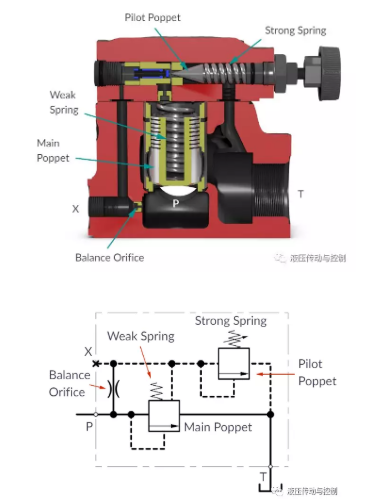
First look at the structural diagram of the balanced relief valve. The pressure relief valve is mainly composed of the main valve Main poppet and the pilot valve Pilot poppet, and both are poppet valve structures. The spring of the main valve is very soft and can basically be compressed by hand, but the spring of the pilot valve is very hard, and the amount of compression needs to be changed by means of an adjustment tool. There is a damping hole between the main oil passage P and the control oil passage X
Symbolic diagram.
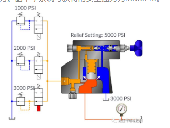
By connecting a constant-pressure relief valve to the control port of the main valve, the system pressure can be controlled remotely. If the pressure setting of the remote control valve is lower than the pressure setting of the pilot valve, the system pressure is determined by the direct-acting relief valve; if its setting value is higher, it is still determined by the pilot valve
In the design of the following example, the remote control valve consists of three groups and the pressure setting value of the relief valve is lower than the setting of the pilot valve of the main valve. The power of any solenoid valve will determine the pressure in the system. In the figure, the safety pressure that the system can obtain is 3000 PSI.
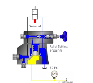
In the following example, when the solenoid valve is energized, the spring-loaded side of the pilot valve is bypassed, which allows the relief valve to work as a relief valve and the system pressure drops to approximately zero
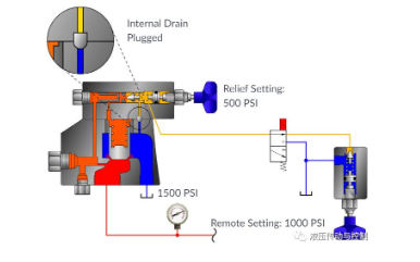
Some relief valves allow the system pressure to be controlled by controlling the pressure on the spring side. As shown in the example, the internal relief port of the main relief valve is blocked. When the solenoid valve is not powered, the system pressure is still determined by the main valve; when the solenoid valve is powered, the system pressure will be the sum of the main valve spring setting and the remote control relief valve setting pressure.